Sunday, May 15, 2011

Wiring the Roaster

Well I had a total brain fart with the thermocouple wire between the roaster and the controller. I installed a two conductor wire thinking that thermocouples only have two wires. However, the MAX6675 chip that converts the analog TC signal to digital signal needs five wires. So I replaced the two conductor wire with a CAT5 cable that I had. Since it is just 5 volt signal going over the wire, the small wire size shouldn't be a problem. One nice thing about this is that I now have extra wires if I want to mount a second TC. I could have an air temp TC and a bean temp TC.


The MAX6675 board and the TC are mounted into the roaster.


Here you can see the thermocouple in the roasting chamber.


The small 5 volt wires were soldered and then topped with wire nuts. It was a bit of a trick to get it all wired and slid together.


I will run it through some tests today and make sure that everything is working. Then I can put the finishing touches on the roaster. As a side note, here is the color coding for the 5 volt wires.

Ground = Blue = -5vdc
VCC = Orange = +5vdc
DO = Green = Arduino Pin 4
CS = Brown/White = Arduino Pin 5
CLK = Brown = Arduino Pin 6

Saturday, May 14, 2011

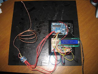
Testing the Thermocouple and LCD

My parts came in the other day, but I was a bit delayed. The LCD display had two rows of 16 pins. That is twice what is listed on the data sheet and what is shown in the pictures and tutorials. Adafruit doesn't really offer phone support, but they are quick to respond to emails. They informed me that both rows of pins are identical so I could use either set. So I soldered and wired everything up. They even have a pre-written sketch for this configuration. It all worked out great and now I am ready to mount the thermocouple and thermocouple card in the roaster. The thermocouple card is much smaller than I thought it would be. That is really quite a nice feature and will make it easy to mount.

Thursday, May 5, 2011

Making the Roaster Enclosure

It's been a while since I posted, but I have been working on this. The roaster enclosure is just about done.


I need the thermocouple and thermocouple card before I can complete it though. I ordered those parts as well as the LCD today. I mounted the main components of the popcorn popper to a piece of press board (cut from an old desk).


Then I purchased a 5 inch stove pipe union for about $5 from the local hardware store. After drilling three rows of vent holes in the bottom half of the stove pipe, I lined the inside with aluminum window screen. Next was to cut up some power cords for the wiring between the roaster and the controller box. I found the cords in my junk bins. The hardware store also had cord strain reliefs for about $0.50 each. I drilled out some holes for the cords and used a file to make them the correct shape. Then I mounted the cords to the stove pipe.


Some more of the old desk was cut to make a ring for the top of the stove pipe. There was a black plastic ring that the popcorn popper chute mounted to. I ground off the mounting studs and then used more aluminum window screen and some black duct tape to make a top for the roaster. This will keep the beans inside the roaster while the fan is running. You can easily see into the roaster while it will be operating. The top can also be easily removed to fill or empty the beans from the roaster.


Followers

About Me

I started making knives when I was thirteen years old (over twenty years ago now). Since then I have made a few hundred knives for friends and family. Most of them I have no photos of. However here are a few that I did manage to get pictures taken of before they left my possession. Since I was about fifteen or sixteen years old, I have been marking my blades with my initials of "DVW".